Hybrid Axial and Cross-Flow Fan Propulsion for Transonic Blended Wing Body Aircraft
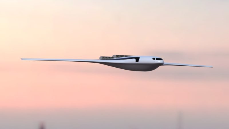
Utilization of embedded, distribution propulsion has the potential to greatly improve the cruise efficiency of next-generation transport aircraft through the ingestion of the low-momentum wake created by the surface of the wings and/or body of the vehicle into the propulsor and re-energizing of the vehicle wake. The blended-wing-body (BWB) vehicle design offers a perfect opportunity to utilize this type of propulsion system, since the majority of the viscous wake is produced by the centerbody section of the vehicle. In addition, the centerbody is thicker and wider than a standard fuselage, providing the space necessary for embedded propulsion.
Ideally, standard fan/engine designs could directly be embedded within the airframe of the vehicle. Unfortunately, doing so causes both performance penalties and structural challenges. For the present design concept, a distributed axial fan system is utilized. This type of propulsor provides excellent compression efficiency when the inflow distribution is uniform (i.e. uniform total pressure and total temperature distribution).
The primary goals of this effort were:
- Development of a basic theory and design procedure for implementing a hybrid Axial fan/Cross-flow fan (AF/CFF) propulsion system into a transonic blended wing body airframe.
- Development of black-box CFD models for both cross-flow fan and axial fan propulsion systems.
- Demonstration, through analytical and CFD calculations, that such a system offers performance gains over a propulsion system utilizing solely distributed axial fans.
- Perform a first-pass analysis of overall system integration.
Black-Box CFF Model
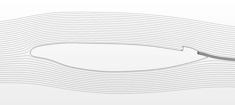
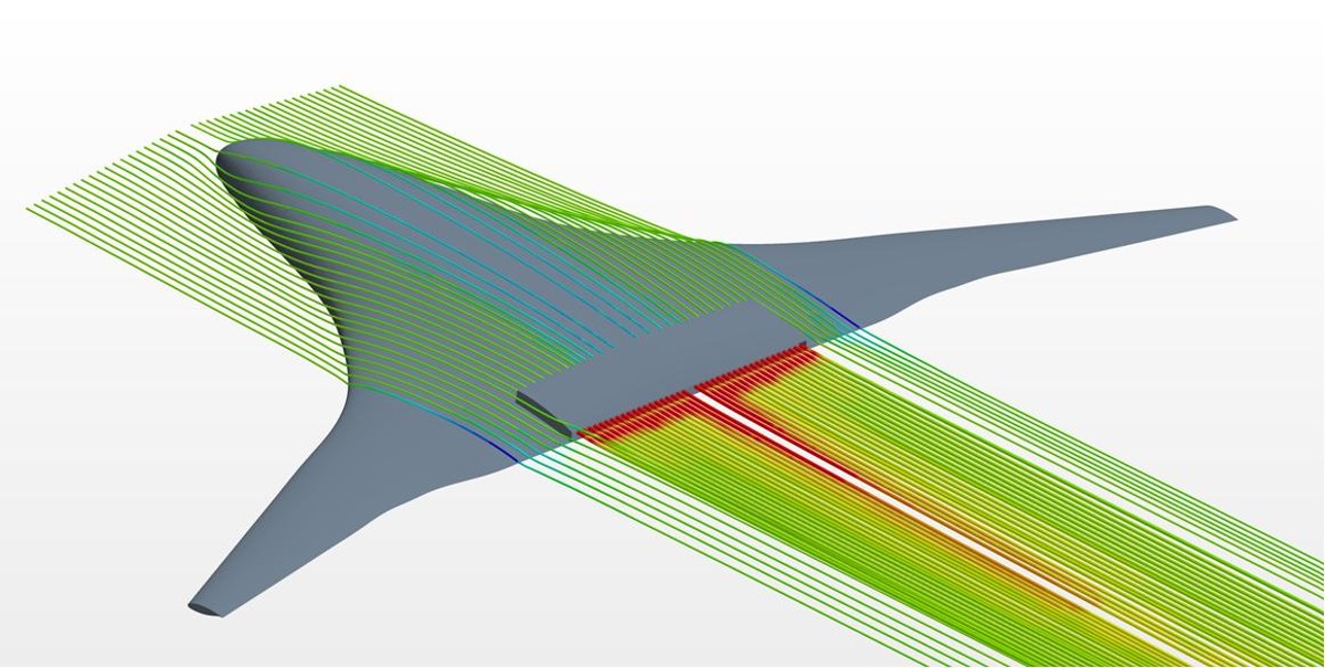
A black-box model was implemented to simulate the effect of the CFF on the external aerodynamics. The model replaces the entire fan and duct by a single inlet and outlet. Within the context of the CFD calculations, the propulsor inlet is simulated as a pressure outlet, while the propulsor outlet is simulated as a stagnation inlet. Each iteration two adjustments are made. The first is at the inlet, where the static pressure at this boundary is modified to bring the mass flow rate into the propulsor inlet (out the pressure outlet boundary) to the desired level. For the baseline cases, this was selected as the mass flow rate corresponding to the CFF-Airfoil simulations previously described; however, the mass flow rate can just as easily be set to any other value. This capability is built into the Star-ccm+ CFD software.
The second adjustment modulates the total pressure and total temperature at the propulsor outlet (i.e. at the stagnation inlet boundary) so that: 1) the mass flow rate remains equal at both the propulsor inlet and outlet, and 2) the total pressure and total temperature rise fall along the performance curves for the fan. Each iteration the mass flow rate is checked. If the mass flow rate at the fan outlet is too high, the flow coefficient is reduced, thus moving the operating point to the left along the total pressure coefficient and compression efficiency curves. Likewise, if the mass flow rate is too low, the flow coefficient is increased. Under-relaxation coefficients were also included in the formulation to stabilize the solution. Once steady-state is reached, the actual operating point for the fan is known, thus allowing calculation of the fan speed and power.
Combined Black-Box Axial Fan and Cross-Flow Fan Model
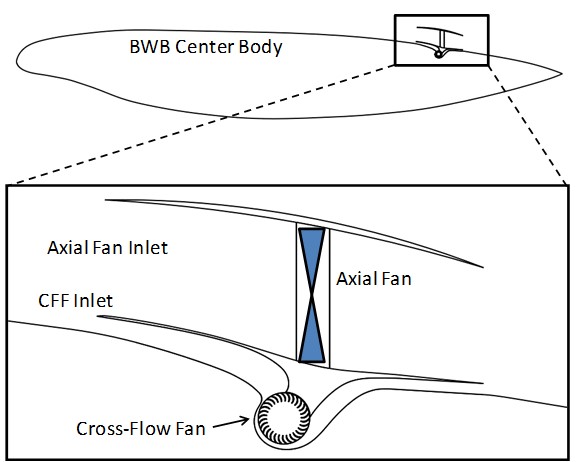
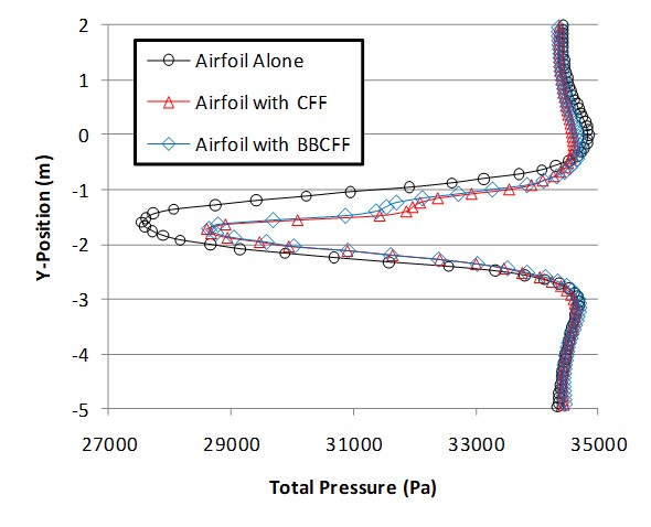
Next the two black-box models were combined into a single CFD calculation. The same baseline geometry was used (i.e. the mid-span airfoil section for the N3-X BWB). The computational mesh contained 87,000 cells. This configuration consists of an axial fan inlet (large inlet) sitting directly on top of a cross-flow fan inlet (small inlet). The goal is to ingest the worst portion of the non-uniform boundary layer flow into the cross-flow fan, allowing the axial fan to “see” cleaner flow. From an analytical perspective, the goal here is to reduce the distortion index at the axial fan inlet, thus increasing the fan performance. There is an inherent tradeoff here, since the cross-flow fan has lower compression efficiency than the axial fan; however, in order to be effective, the CFF inlet need only ingest 4-6” of the boundary layer, thus contributing to only a small portion of the overall power consumption.
Cases were run across a range of inlet and outlet heights in order to assess the capabilities of the CFD models, as well as evaluate the power requirements of this configuration. Although the 2D flow field will inherently be different than for the 3D case, the trends should remain intact. In addition, the development of 2D simulation techniques offers an excellent option for future design efforts.
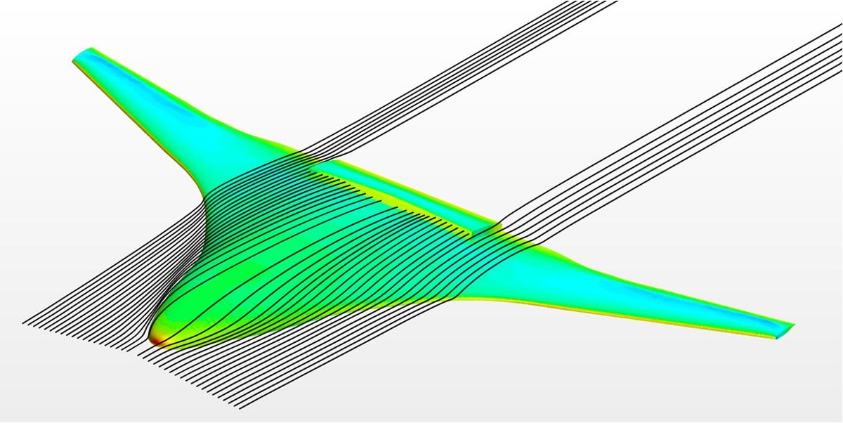
Several 3D BWB cases were simulated in Star-ccm+. All of the geometries were first constructed in Solidworks, and then exported into the CFD software package. The baseline BWB geometry was given to Propulsive Wing by NASA as a starting point. This geometry consisted of the spanwise airfoil sections. Taking this data into Solidworks, new lofts were created to approximate the actual smoothed contours of the vehicle.
System Layout, Finite Element Analysis, and Preliminary Weight Estimate
A preliminary calculation was performed to demonstrate the analysis method, as well as provide a baseline, for the weight of the CFF propulsion system. The same 12" diameter CFF was used in these calculations as was used previously for the CFF-Airfoil simulations. The width of the CFF inlet was assumed to be equal to the width of the rectangular AF inlet, here taken as 4 ft. A CAD model showing the basic layout for the system is given below. Composite cross-flow fans were manufactured from a combination of quasi-isotropic carbon fiber flat plates (for the end and divider plates) and pultruded carbon fiber blade sections. This manufacturing process works well for this type of fan, since the greatest forces are in the radial direction. The pultruded carbon fiber offers very high bending stiffness to weight ratio. The fan shown is 12” diameter and 47.5” long. The weight is approximately 27 lbs.
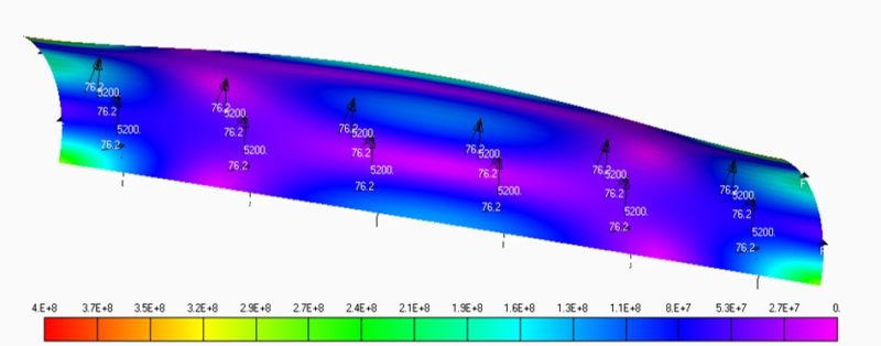
To establish a structural baseline for the fan blades, an FEA calculation was performed for a single blade segment. The blade section was assumed to span only 12”. From one of the CFF-Airfoil CFD simulations, the x and y aerodynamic force components were extracted as functions of azimuth angle (with zero degrees taken horizontally toward the outlet). For the present case, the maximum aerodynamic force is about 250 N/m. By contrast, for the 12” blade segment simulated here, the centrifugal force at 6,000 rpm is approximately 5,200 N. Thus the centrifugal force will be a major driving factor for the structural design of the blades. To further investigate this, an FEA calculation was setup corresponding to the aforementioned 12” blade segment. The ends were set as fixed boundary conditions. A 76.2 N load was applied normal outward from the surface to approximate the aerodynamic loading. A 5,200 N load was also applied to the blade in the y-direction to simulate the centrifugal force. The image below shows the von Mises stresses for the blade segment. Clearly there is a large amount of deformation due to the centrifugal force. The stresses at 300-400 MPa are also fairly high. Although pultruded carbon fiber can typically reach 1-1.5 GPa stress levels without problems, this may not be an acceptable safety factor for the system.
To read the full technical report, funded by NASA Glenn Research Center through a Phase 1 SBIR, click the pdf link to the right. If your organization has a challenging structural or aerodynamics challenge, call or email us to find out how we can help.
